
Installing the Adapter to Panel
This section describes how to install the wired adapter to the panel and connect it to the GPH6000 Series wired type.
 DANGER DANGER |
|---|
|
HAZARD OF ELECTRIC SHOCK, EXPLOSION, OR ARC FLASH
Failure to follow these instructions will result in death or serious injury.
|
| NOTICE |
|---|
|
EQUIPMENT DAMAGE
Failure to follow these instructions can result in equipment damage.
|
| NOTICE |
|---|
|
EQUIPMENT DAMAGE
Do not allow the cable's connector to drop or hit against
anything hard.
Failure to follow these instructions can result in equipment damage.
|
Prepare the dedicated cable in advance. For instructions on how to attach the cable to the product, refer to Installing the Dedicated Cable.
Wired adapter connection cable package contents
A. Installation screw (M3) x 5
B. Cable x 1
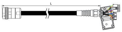
PFXZHCBLCOM5M
L = 5,000 ±100 mm (196.85 ±3.94 in)
PFXZHCBLCOM10M
L = 10,000 ±100 mm (393.70 ±3.94 in)
PFXZHCBLCOM20M
L = 20,000 ±100 mm (787.40 ±3.94 in)
Installation Procedure
- Based on the product's Panel Cutout Dimensions, cut out a mounting hole on the panel.
- Remove the nut from the adapter.
- Attach the supplied gasket to the cable connector on the adapter.
- Insert the cable connection part of the adapter from the back side of the panel.
- Affix the product to the panel with the screws (included).
For instructions on how to use the screws, refer to the Panel Cutout Dimensions. Tighten the installation screws
clockwise with a screwdriver (Ph2). The necessary torque is 0.6 N•m
(5.3 lb-in).
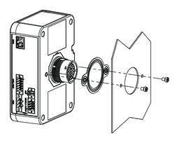 NOTE: If using only one screw, install the nut.
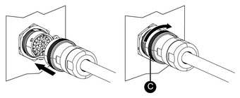
- Connect the cable. Check the shapes of connectors to attach
them in the correct orientation. Turn the lock ring in the direction
of the arrow to secure the cable.
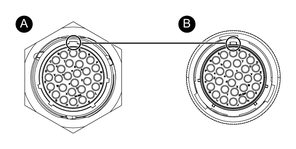
-
Connector on the adapter side
-
Connector on cable side
-
Lock ring
-