
Wiring the Direct Connection Cable
 DANGER DANGER |
|---|
|
HAZARD OF ELECTRIC SHOCK, EXPLOSION, OR ARC FLASH
Failure to follow these instructions will result in death or serious injury.
|
 DANGER DANGER |
|---|
|
SHORT CIRCUIT, FIRE, OR UNINTENDED EQUIPMENT OPERATION
Properly terminate unused wires to help avoid short-circuits
by other signals or metal parts.
Failure to follow these instructions will result in death or serious injury.
|
Cable Specifications
Direct connection cable package contents
A. Installation screw (M3) x 5
B. Cable x 1
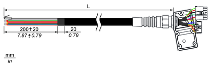
PFXZHCBLOUT5M
L = 5,000 ±100 mm (196.85 ±3.94 in)
PFXZHCBLOUT10M
L = 10,000 ±100 mm (393.70 ±3.94 in)
|
Connection destination |
Signal name |
Cable color |
Cable diameter (outer diameter) |
Wire gauge |
Twisted pair*1 |
|---|---|---|---|---|---|
|
Power supply |
24 Vdc |
Brown |
1.7 mm |
AWG 18 |
|
|
0 Vdc |
White |
1.7 mm |
AWG 18 |
||
|
FG (functional ground) |
Black (Shield) |
1.0 mm |
Φ1.0 mm |
||
|
Emergency stop switch |
EMG1A |
Yellow |
2.0 mm |
AWG 16 |
|
|
EMG1B |
Green |
||||
|
EMG2A |
Grey |
||||
|
EMG2B |
Pink |
||||
|
Enabling switch |
ENB1A |
Red |
1.25 mm |
AWG 22 |
|
|
ENB1B |
Blue |
||||
|
ENB2A |
Black |
||||
|
ENB2B |
Violet |
||||
|
Key switch |
Key_NO |
White/Green |
1.25 mm |
AWG 22 |
|
|
Key_NC |
Grey/Pink |
||||
|
Key_COM |
Red/Blue |
||||
|
Serial interface |
DTR (RS-232C) |
Brown/Green |
1 mm |
AWG 26 |
1 |
|
DCD (RS-232C) |
Grey/Brown |
1 |
|||
|
DSR (RS-232C) |
Yellow/Brown |
2 |
|||
|
RI (RS-232C) |
White/Yellow |
2 |
|||
|
TX (RS-232C)/TXP (RS-422/485) |
White/Pink |
3 |
|||
|
RX (RS-232C)/RXP (RS-422/485) |
White/Blue |
4 |
|||
|
RTS (RS-232C)/TXN (RS-422/485) |
Pink/Brown |
3 |
|||
|
CTS (RS-232C)/RXN (RS-422/485) |
Brown/Blue |
4 |
|||
|
SG |
White/Gray |
||||
|
Ethernet interface |
TX+ |
Yellow |
1.05 mm |
AWG 26 |
5 |
|
RX+ |
White |
6 |
|||
|
TX- |
Orange |
5 |
|||
|
RX- |
Blue |
6 |
*1 Twist the together the same numbered cables.
The direct cable has an RJ-45 connector for the Ethernet interface. The other cables are loose wires, each with a ferrule terminal.
The specifications of each ferrule terminal are as follows;

|
Ferrule terminal |
Wire gauge |
Connection destination |
|---|---|---|
|
L2 = 6 mm, d2 = Φ0.8 mm |
AWG 16 |
Emergency stop device |
|
L2 = 8 mm, d2 = Φ1.2 mm |
AWG 18 |
Power supply unit |
|
L2 = 8 mm, d2 = Φ1.7 mm |
AWG 22 ~ 26 |
Enabling device, host controller, etc. |
Connecting the DC Power Cord
-
The SG (signal ground) and FG (functional ground) terminals are separated internally in this product.
-
When the FG terminal is connected, be sure the wire is grounded. Not grounding this product can result in excessive electromagnetic interference (EMI).
-
For more information about power connections, refer to Wiring the Power Supply.