
Installation Procedure
 DANGER DANGER |
|---|
|
HAZARD OF ELECTRIC SHOCK, EXPLOSION, OR ARC FLASH
Failure to follow these instructions will result in death or serious injury.
|
| NOTICE |
|---|
|
EQUIPMENT DAMAGE
Failure to follow these instructions can result in equipment damage.
|
- Check that the gasket is seated securely into the bezel's
groove, which runs around the perimeter of the display panel frame.NOTE: Always use the installation gasket, since it absorbs vibration in addition to repelling water. For the procedure on replacing the installation gasket, refer to Replacing the Installation Gasket.
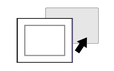
- Cut the panel opening based on the specified Panel Cutout Dimensions, and insert the product from the
front of the opening.
 NOTE: This product has an anti-drop lock at the top to prevent it from falling. Insert the bottom part of the product into the panel opening, and then insert the top part while pressing the unlock button.
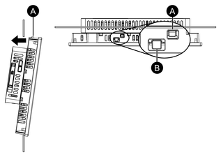
-
Anti-drop lock
-
Unlock button
-
- Insert the installation fasteners into the bracket openings
at the top, bottom, left and right, and tighten the M4 screws little
by little, alternating between diagonally-positioned screws.NOTE: The necessary torque is 0.7 N•m (6.2 lb-in).

-
Panel
Number of Installation Fasteners
The number of installation fasteners for each model is as follows.
10-inch, 12-inch, 10-inch wide, 12-inch wide Top - 2, Bottom - 2 15-inch, 15-inch wide, 19-inch wide, 22-inch wide Top - 3, Bottom - 3, Left - 1, Right - 1 -