How Alarms Work
The Transition Between Alarm States
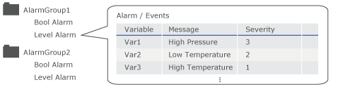
Alarm Data Structure
There are two types of alarms, Bool Alarm and Level Alarm, for which you can set up a variable to monitor, message to display, severity, and so on.
| Type | Description | Available Variable Data Types |
| Bool Alarm | Alarm occurs depending on the ON or OFF value of the variable that is monitored. |
BOOL |
| Level Alarm | Alarm occurs depending on the stored value of the variable that is monitored. | SINT, USINT, INT, UINT, DINT, UDINT, LINT, ULINT, BYTE, WORD, DWORD, LWORD, REAL, LREAL. |
You can display alarms by alarm groups in Alarm Summary objects.
- For the number of alarm groups you can create, refer to the
following.
Supported Model/Feature - External variable values are updated based on the Scan Rate
interval. When an external variable is set up with an alarm, and
the Scan Rate interval is too long, there may be a considerable
time lag from when an alarm is generated by the external device,
to when the alarm is displayed on the Alarm Summary object. For
information about scan rates, refer to the following.
Setting the Interval for Reading External Variable Values (Scan Rate) - For information about Alarm Summary object, refer to the following.
Display Alarms
Alarm Workflow
- In the screen editing software, create an alarm.
By using the import/export function, you can use Excel or other spreadsheet tools to edit alarms. For details, refer to the following.
- Transfer the project to the display unit.
- Check the alarm information of active alarms in the Alarm Summary
object and touch the [ACK] switch.
Information in the Alarm Summary object is updated (changed to acknowledged).
- When the value of the monitored variable returns to normal, information in the Alarm Summary object is updated (changed to recovered).
About Saved Alarms
Alarms are saved to the defined [Save in] field.
[Save in] |
Description |
| [Backup Memory] | Data is stored in the display unit's backup memory (SRAM). |
| [SD Card] | Data is stored in the display unit's SD Card. |
| [USB Storage] | Data is stored in the display unit's USB storage. |
Alarms are saved in binary format.
You can check the data from the Project Explorer by clicking [System Architecture] and selecting [All Alarms].
For data size calculation, see the following.
Calculating the Size of Data to Save
You can select from the following on how to operate after reaching the specified [Maximum Number of Records].
- Stop Logging
- Overwrite Old Data
The Transition Between Alarm States
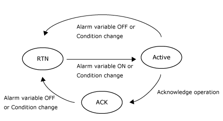
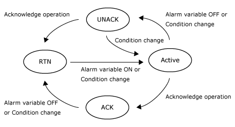
Depending on the setting in the [Alarm Behavior] property, the alarm status transitions between either three states ([Optional ACK]) or four states ([Mandatory ACK]).
- 3 states ([Optional ACK]): Transition between the Active, Acknowledged
and Return-to-Normal (RTN) states, and Acknowledging alarms is optional.
- 4 states ([Mandatory ACK]): Transition between the Active, Acknowledged,
Unacknowledged and Return-to-Normal (RTN) states. Acknowledging alarms
is mandatory before it can enter the Return-to-Normal (RTN) state.
For information on the [Alarm Behavior] property, see the following.