 1.1.3 For Those Using a Display Unit Supporting GP-Pro EX Ver.5.00 and Later
The following are the precautions for the GP6000 series.
1.1.3 For Those Using a Display Unit Supporting GP-Pro EX Ver.5.00 and Later
The display unit is equipped with System Settings separate from offline mode. For details about System Settings, refer to the manual for the display unit.
The [Timezone] in the [System Settings] - [Date and Time] is ignored.
The [DNS Settings] in the [System Settings] - [Ethernet] are ignored.
When the [System Settings] - [Ethernet] - [IP Mode] is set to [Auto], the display unit automatically obtains an IP address when connected to the network but cannot resolve names because the [DNS Settings] are ignored. When you specify the display unit from the Transfer Tool or other means, specify the IP address displayed in [System Settings] - [Information].
Pro-face Remote HMI clients cannot browse the display unit’s System Settings screen. When the display unit displays the System Settings screen, the client displays the screen previously shown before it changed to the System Settings screen. In addition, you cannot switch to the System Settings screen in the Remote HMI Client, even if you touch the [System Settings] button in offline mode.
If you use a display unit with matrix touch panel technology, the size of each switch should be 25x25 pixels or larger. To draw in 25 dot increments, from the [View] menu, select [Preferences]. In the dialog box, select [Screen Edit Style]. In the [Grid] tab, select the [Snap to Grid] check box to select a 25x25 dot grid.
For the features supported and unsupported by GP6000 Series, refer to Supported Features.
1.4.1.2 GP6000 Series (Standard Models)
1.4.1.3 GP6000 Series (Advanced Models)
The integer type logic system variable #L_Version is not supported.
A.2.1.2 Integer Type Logic System Variables - #L System Variables
When using PDF Viewer with the GP6000 Series (standard model), to transfer a project with PDF Viewer set the first time, you must transfer the project twice.
Displaying and Operating the [Welcome] Screen
The following methods are used to display and operate the [Welcome] screen on the GP6000 Series.
For the GP6000 Series (except GP6B40):
When you first turn ON the power after you purchase the display unit, the GP6000 Series setup screen appears. For the setup procedure, refer to the GP6000 Series hardware manual. The [Welcome] screen appears after you register an administrator account. Touch the [Agree] button.
For the GP6B40:
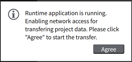
For the GP6B40 without a connected display, run setup through a computer. For the setup procedure through a computer, refer to the GP6000 Series hardware manual. The following screen appears after you register an administrator account. Click the [Agree] button.
Using an Expansion Unit
You can expand the features of the GP6000 Series (Advanced Models) by installing the following expansion units.
Serial interface expansion unit
Ethernet interface expansion unit
AUX interface expansion unit
Backup memory expansion unit
The number of expansion units that can be installed to a display unit are as follows.
PFXGP6B40*: Up to 5
Models other than the above: Up to 2
You cannot install multiple interface expansion units of the same model to a display unit. You may install up to two backup memory expansion units. For details, refer to the manual for your expansion unit.
If the actual hardware configuration (display unit, expansion unit, and external devices) does not match the configured expansion interface functions, those functions will not operate correctly. For example, if you configured the settings to output the touch buzzer sound to an external device but an AUX interface expansion unit has not been installed on the display unit, or the expansion unit does not have a speaker, the buzzer sound will not play and an error message will not be displayed.
Do not remove or replace a backup memory expansion unit during system operation. For more details, please refer to the following.
4.6.7 Restrictions When Using Expansion Unit