Merge Shapes
You can combine multiple shapes and icon objects into one path object using the [Merge Shapes] feature.
Merge Objects
- Select the objects you want to merge on the screen.
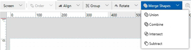
- Select the type of operation from [Merge Shapes].
- The Fill, Border, and Border Thickness settings for the created shape will be the same as the first selected object.
- The [Merge Shapes] feature does not work with following Screens/Contents.
- Dock Panel
- Stack Panel
- Uniform Grid
- The [Merge Shapes] feature does not work if the following shapes are included.
- Grouped Object
- Bar Scale
- Circle Scale
- Image
- Line
- Path (SVG file used)
- You can combine icon images from [Icons] with shapes. The following is an example of combining [Home01] and a [Rectangle] using [Subtract].
Example2.png)
Types of Combinations
Union
Merge two or more shapes to create a single Path object.

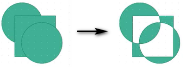
Combine
Remove the overlapping areas of shapes to create a single path object. The areas of shapes that overlap with the removed area are included in the resulting path object.
Intersect
Create a single path object using only the area that overlaps all the shapes.
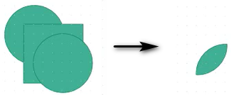
If the result is too small to display, an error message appears.
Subtract
From the first shape, subtract the area of subsequent shapes to create a single Path object.
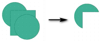
If multiple objects are selected while holding down the [CTRL] key, the area of subsequent objects is cut off from the first selected object.
Animation Display Examples of Merged Shapes
By combining [Merge Shapes] with animations, you can create dynamic objects like the following:
Tank with Text
- Combine ellipses and a rectangle using [Union].
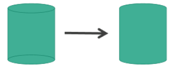
- Combine a cylinder and text using [Combine].

- By setting animations on the generated path object, you can represent the tank’s fill level, including the text part. Below is an example where the fill level changes vertically based on the value of the variable Var1.

Path object properties:
| Tab | Sub Tab | Property | Value | |||
|
[Shape] |
[Size/Location] |
[Animation] |
[Fill Level] | [Enable] |  |
|
| [Vertical Fill] |
|
|||||
| [Vertical Start Point] | [Bottom] | |||||
 [Variable]
Level Meter
- Duplicate rectangles in the X direction, select all, and perform [Union].
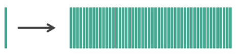
- Combine the generated path object with an ellipse and perform [Subtract].
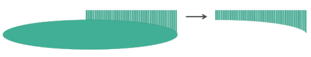
- Combine the generated path object with an ellipse and perform [Intersect].

- By setting animations on the generated path object, you can represent the level. Below is an example where the fill level changes horizontally based on the value of the variable Var1.
Path object properties:
| Tab | Sub Tab | Property | Value | ||
|
[Shape] |
[Size/Location] |
[Animation] |
[Fill Level] | [Enable] | |
| [Horizontal Fill] |
|
||||
| [Horizontal Start Point] | [Left] | ||||