
Attaching the VESA Mounting Plate
| NOTICE |
|---|
|
EQUIPMENT DAMAGE
Do not exert more torque than the amount specified.
Failure to follow these instructions can result in equipment damage.
|
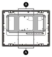
- Place the product on a clean and level surface with the screen facing down.
- Remove the four screws on the rear face.
M3 screws, length: 30 mm (1.18 in)

- Align the screw holes on the VESA mounting plate with the
screw holes on the BOX module, then secure the plate using the four
screws included in the package.
M3 screw, length: 39 mm (1.53 in)
NOTE:-
Please use the correct screws.
-
The necessary torque is 0.5 N•m (4.4 lb-in).

-
Mounting/Removing the Product on Monitor Arm
Use the four M4 screws to attach the product to the commercially available monitor arm or wall-mount adapter.
-
VESA mounting screw holes
-
The effective thread depth of the screw holes on the VESA mounting plate is 10 mm (0.39 in) or less.
-
The maximum tightening torque is 1.0 N•m (8.9 lb-in). Please check the specified torque values for the arm or adapter you are using, and tighten the screws to the appropriate torque.
 CAUTION CAUTION |
|---|
|
RISK OF INJURY, EQUIPMENT DAMAGE
Failure to follow these instructions can result in injury or equipment damage.
|