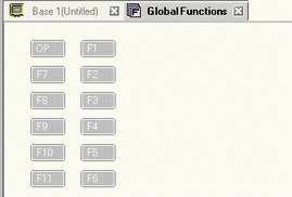
In the [Common Settings (R)] menu, click [Global Function Settings (C)], and the following screen appears. Double-click the function key to which you want to allocate the feature. (For example, F1)
![]()
-
The number of displayed function keys depends on the display unit model.
-
You can also add functionality to the Operation Switch (OP).
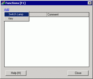
In the message box that appears, click [Yes (Y)].
Select [Switch Lamp].
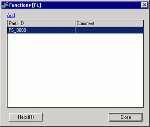
A part ID is added to the dialog box. Double-click the ID to display the [Switch/Lamp] dialog box.
![]()
-
To delete registered parts, right-click the part you want to delete. From the popup menu, select [Delete].
Set up the [Window Display Switch] and click [OK].
![]()
-
See the following for information on setting up Switches.
 10. Switches
 -
The hand-held GP depends on serial communication for the Conversion Adapter's external buzzer output or DOUT output. As a result, there may be a delay of approximately 100 ms from when the switch is pressed to when the signal actually outputs. However, if there is lot of noise and communication is poor, then the delay may reach up to 200 ms. If communication is not successful within 200 ms, then a timeout error will occur.
-
The external buzzer is output by both Function Keys and screen touches.
-
The sound of the external buzzer is linked with the sound of the touch buzzer.
[Close] exits the function settings dialog box.
![]()
-
Function keys display in black text when they have operations set up.
-
You can acknowledge function key operations during simulation.
-
The operation switch is not available during simulation.