
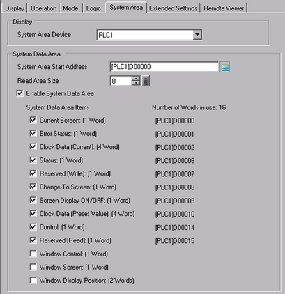
Please refer to the Settings Guide for details.
 5.4.6 System Settings [Display Unit] - [System Area] Settings Guide
5.4.6 System Settings [Display Unit] - [System Area] Settings Guide
 A.1.1.2 System Data Area (Direct Access Method) or A.1.2.2 System Data Area (Memory Link Method)
A.1.1.2 System Data Area (Direct Access Method) or A.1.2.2 System Data Area (Memory Link Method)
In the [Project] menu, click [System Settings] and then click [Display Unit]. Open the [System Area] tab.
Select which device/PLC to allocate the system data area in [System Area Device].
Designate the start address of the system area in [System Area Start Address] and select the [Enable System Data Area] check box.
Select the [Control:(1 Word)] check box.

If you turn ON Bit 1 in the [Control: (1 Word)] address specified while Bit 4 is OFF, the display unit buzzer rings.


If you turn ON Bit 1 while Bit 4 is ON, the buzzer will not ring.
Control Word Address: Bit 4 controls output to buzzer (0) or does not output to buzzer (1)
 A.1.1.2 System Data Area (Direct Access Method) or A.1.2.2 System Data Area (Memory Link Method)
A.1.1.2 System Data Area (Direct Access Method) or A.1.2.2 System Data Area (Memory Link Method)